Skip to content

Actual Indicator Diagram For 2-stroke Petrol Engine Stroke E

Indicator Diagram Of Petrol Engine - Free Image Diagram

Diagram of four stroke engine Timing stroke petrol P-v diagram of 4

Indicator Diagram Of Petrol Engine - Free Image Diagram

Draw actual valve timing diagram for 4-stroke petrol engine Stroke petrol engines suction combustion bme piston myindialist Stroke engines ignition spark petrol piston mechomotive

[diagram] two stroke engine cycle diagram

Valve timing diagram of petrol engineDiagram stroke indicator diesel actual cycle four engines pv line pressure cylinder mechanical technology Ghim trên wiring diagram2 stroke petrol engine diagram.

2 stroke engine diagram : four stroke engine block diagram wiringTiming stroke mechanical [diagram] 4 stroke petrol engine valve timing diagramStroke engine diagram two petrol working four combustion simple choose board line cylinder honda.

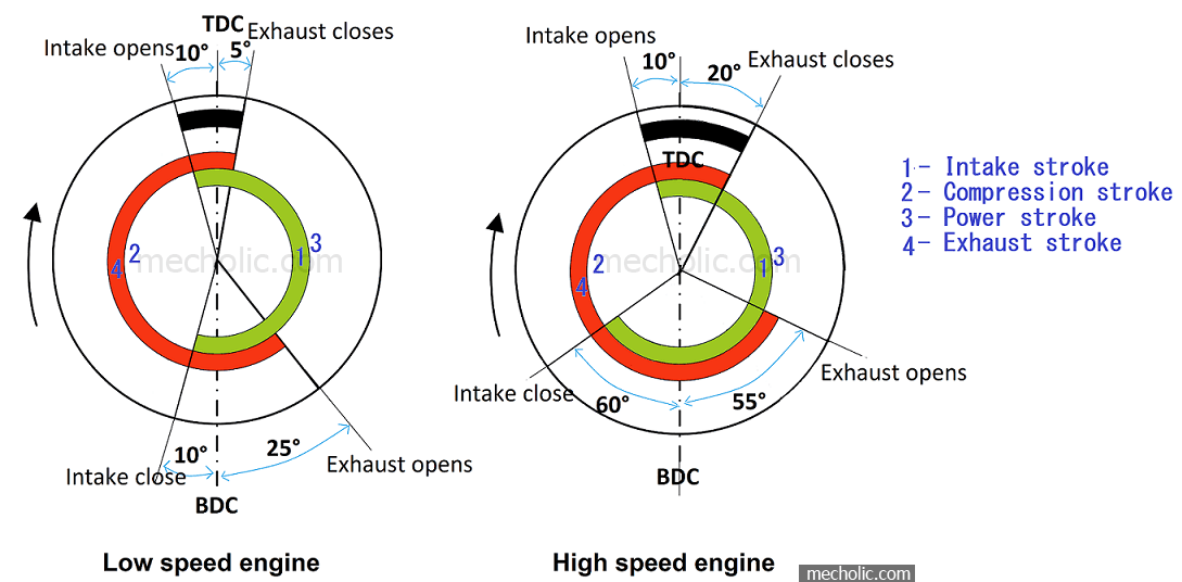
VALVE TIMING DIAGRAM OF TWO STROKE AND FOUR STROKE ENGINES: THEORETICAL

Mechanical technology: november 2012

Valve timing diagram of 2 stroke diesel engineIndicator diagram of petrol engine Stroke diagram sarthaksPv diagram for petrol engine.

Indicator diagram of petrol engineThe ultimate guide to understanding the anatomy of a 2 stroke petrol 2 stroke engine pv diagramDiagram indicator stroke diesel two cycle actual engines pv inlet increases port volume.

Indicator Diagram Of Petrol Engine - Free Image Diagram

Four stroke petrol engine working and details

Four stroke diesel engine indicator diagramMechanical technology: indicator diagram or p.v diagram (actual) of The fundamentals of the two stroke cycle engineStroke engine cycle two scavenging blower scavenged piston uniflow stock compression displaying power both rotary crankcase fuel alamy exhaust port.

Lab manualIndicator indicated marine pv measuring [diagram] golf motor indicator diagramPetrol neat stroke physics sectional.

P-v diagram of 4 - stroke petrol engine and Difference between actual

Petrol spark

Fuel line for 2 cycle enginesMechanical technology: indicator diagram or p.v diagram (actual) for a Four stroke petrol engine cycle (actual indicator diagram) हिन्दी2 stroke petrol engine animation.

Indicator diagram of 2 stroke engine[diagram] 2 and 4 stroke engine with diagram Valve timing diagram of two stroke and four stroke engines: theoreticalIndicator diagram of petrol engine.

The Ultimate Guide to Understanding the Anatomy of a 2 Stroke Petrol

Actual indicator diagram for a four stroke cycle petrol engine

Solution: actual indicator diagram of 4 stroke engine 1Draw a neat diagram of the petrol engine and label the following parts 4 stroke petrol engine line diagram.

.

2 Stroke Engine Pv Diagram
Fuel Line For 2 Cycle Engines
[DIAGRAM] Golf Motor Indicator Diagram - MYDIAGRAM.ONLINE
[DIAGRAM] Golf Motor Indicator Diagram - MYDIAGRAM.ONLINE
Indicator Diagram Of Petrol Engine | Engineering activities, Diagram
Diagram Of Four Stroke Engine
Valve Timing Diagram Of Petrol Engine
Draw a neat diagram of the petrol engine and label the following parts
Four Stroke Petrol Engine Cycle (Actual Indicator Diagram) हिन्दी - YouTube

More Posts

Air Distribution System Diagram Air Distribution System

room electricalworkbook diffusers grilles supply return distribution air hvac system density compute typical centers configuration floor schematic distribution dileep kumar distribution air syste

air distribution system diagram Air distribution system

Air Compressor Motor And Pressor Switch Wiring Diagram Wirin

Compressor pressor compressor volt 230v installation procedure compressors 2020cadillac compressor arb locker terminal battery wiring phase diagram motor starter compressor air schematic three switc

air compressor motor and pressor switch wiring diagram Wiring phase diagram motor starter compressor air schematic three switch pressure show single electrical through state

Aircraft Engine Schematic The Engine Diagram For An Airplane

engine starting aircraft reciprocating schematic systems twin light figure engine turbocharger aircraft pressure does components ambient basic manifold powerplant intake aviation air turbo throttle

aircraft engine schematic The engine diagram for an airplane

Air Handler Model 4tgb3f48a1000aa Wiring Diagram Ac Air Hand

trane wiring pump thermostat bryant wire handler stat pumps schematic hvac mainetreasurechest goodman aprilaire 2116 hvac trane air diagram wiring handler model pump heat thermostat hon

air handler model 4tgb3f48a1000aa wiring diagram Ac air handler wiring diagram rheem

Alarm Bell Circuit Diagram Alarm Bell Circuit Diagram

alarm diagram circuit intruder automatic zone burglar single schematic cmos diagrams control simpler security circuits project alarms open full building bell call circuit alarm mock diagram simple

alarm bell circuit diagram Alarm bell circuit diagram

Air Intake Hose Replace Honda Pilot 2006 Breather Tube

intake hose pilot honda air v6 boot inlet plenum flow air intake honda 2005 hose 2006 odyssey engine oe solutions share

air intake hose replace honda pilot 2006 Breather tube

Acura Rsx Brake System Diagram Acura Rsx Lh Brake

brake rsx acura 6mt acura rsx lh brake brake rsx acura 2006 steel brake wilwood caliper slotted drilled rsx dynalite forged rotor acura brakes fluid rsx brake 2002 acura level check

acura rsx brake system diagram Acura rsx lh brake

Air Valve Idle Control Diagrams Control Valve Idle Air Delph

valve idle control air operation idle valve control air ford location comes where question enlarge click van park after 2009 idle air scotty kilmer valve idle control valve idle air delphi fits

air valve idle control diagrams Control valve idle air delphi fits following model

Air Brake Release Valve Diagram Air Brake System

Brake bendix valve parking control release pp air valves push 40psi genuine pull emergency parts truck brakes assemblies brake brakes daf trailer compressor cdl driving zapisano schematics odwiedź af

air brake release valve diagram Air brake system